Creative and daring ways
Multi-Offset VSP inversion for
CO2 sequestration monitoring
CO2 sequestration monitoring
This case study has been presented in a EAGE/SEG Research Workshop 2017, in Trondheim (Norway).
Borehole seismic monitoring for virtual CO2 injection site
To demonstrate the feasibility of the multi-Offset VSP inversion for CO2 sequestration monitoring, we propose a synthetic seismic experiment based on the reservoir simulation results and the derived velocities anomalies for a virtual CO2 injection site (Tsuchiya et al, 20171).
Tsuchiya et al. studied a virtual CO2 injection site within the area F3 block in the Dutch sector Southern North Sea. An injection well is assumed to be drilled to a position within an interpreted sand-rich formation. Interval of the defined injection formation at the pseudo well is 855-930m. A monitoring experiment has been designed to evaluate the applicability of elastic FWI of VSP data for CO2 injection monitoring. The goal is to extract two independent physical parameters from the data, namely P- and S-wave velocities in order to determine the pore-pressure and CO2 saturation effects within the reservoir. A suitable acquisition geometry for the monitoring is a multi-offset VSP. The MO-VSP consists of 10 shots located every 200m (no zero offset shot) with a vertical antenna from 300 down to 1200m and a 10m geophone interval. In this study, only the vertical component is recorded to evaluate also the possibility of a fibre optic system deployment instead of classical multi-component geophones.
Timelapse Elastic Full Waveform Inversion
The timelapse elastic FWI consists, first, in inverting the baseline MO-VSP seismic data acquired prior to any CO2 injection to obtain the estimated baseline model. Then starting from this baseline model, invert the monitor MO-VSP seismic data acquired after a certain interval of time of CO2 injection (3 years in our case) to obtain the estimated monitor model. The following figure summarizes the timelapse elastic FWI approach.
The timelapse elastic FWI consists, first, in inverting the baseline MO-VSP seismic data acquired prior to any CO2 injection to obtain the estimated baseline model. Then starting from this baseline model, invert the monitor MO-VSP seismic data acquired after a certain interval of time of CO2 injection (3 years in our case) to obtain the estimated monitor model. The following figure summarizes the timelapse elastic FWI approach.
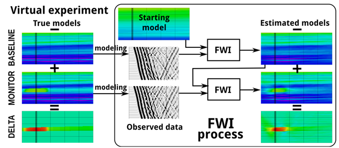
The colored images zoom on the reservoir zone where small triangles represent the geophones of the antenna (see Figure 2). The BASELINE indicates the model/data before injection while MONITOR denotes the model/data after 3 years of CO2 injection. For better display purposes, DELTA is the difference between MONITOR and BASELINE. Baseline and monitor observed data for FWI are obtained by modelling wave propagation, respectively in the baseline and monitor true models. The estimated baseline model is obtained by applying FWI on baseline observed data and using the Starting model. The estimated monitor model is obtained by applying FWI on the monitor observed data and starting from the estimated baseline model.
Baseline elastic FWI before injection
The results of the elastic FWI applied on the baseline observed data are plotted in the middle column of the following figure. The difference between the estimated models and the true models (Right) shows that the inversion process is able to recover with reliability both P- and S-wave velocity parameters in the illuminated region from the sources to the receivers. One can increase the illuminated region by using more offsets or deeper antenna but a few hundreds of meters are a typical lateral resolution for borehole seismic data.
The results of the elastic FWI applied on the baseline observed data are plotted in the middle column of the following figure. The difference between the estimated models and the true models (Right) shows that the inversion process is able to recover with reliability both P- and S-wave velocity parameters in the illuminated region from the sources to the receivers. One can increase the illuminated region by using more offsets or deeper antenna but a few hundreds of meters are a typical lateral resolution for borehole seismic data.
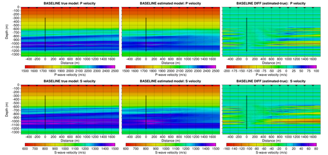
The P-wave velocity fields are displayed on the top row while the S-wave velocity fields are on the bottom row. Left, the true models; Middle, the FWI estimated models and Right the difference between the estimated and true models. The acquisition geometry for the MO-VSP is denoted by stars at the surface for the 10 sources, and small triangles in the vertical well for the geophones.
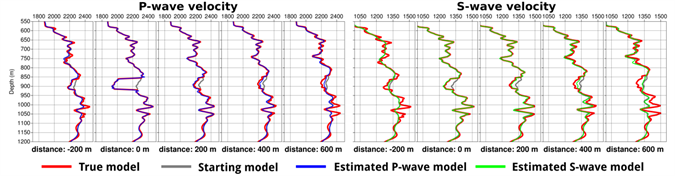
The detailed results are presented in vertical profiles for different offsets from the well in the following figure. The fit is very good between 0 and 400 m from the well.
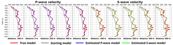
Left: P-wave velocity profiles; Right: S-wave velocity profiles. The different plots correspond to different distances from the well. The starting model, denoted by the gray line, is underestimated. The true model is denoted by the red line while P- and S-wave velocities are denoted respectively by the blue and the green lines. The fit between estimated and true model is good from 0 to 400 m for P velocity and from 0 to 300 m for S velocity because of the narrower illuminated region for S due to P-S conversion angles.
Monitor elastic FWI after 3 years injection
The 3-year timelapse monitoring experiment is based on the reservoir perturbations of P- and S-wave velocities and density fields in the reservoir are based on the estimation obtained by Tsuchiya et al. (2017). The results of the FWI applied to the monitor data are displayed in the following figures. The extension of the perturbation on the left side of the well is not sufficient due to lack of shots on this side (only 2) and the extension on the right side is correct up to 300 m from the well. This allows us to predict the CO2 saturation and the pore pressure within this interval.
The 3-year timelapse monitoring experiment is based on the reservoir perturbations of P- and S-wave velocities and density fields in the reservoir are based on the estimation obtained by Tsuchiya et al. (2017). The results of the FWI applied to the monitor data are displayed in the following figures. The extension of the perturbation on the left side of the well is not sufficient due to lack of shots on this side (only 2) and the extension on the right side is correct up to 300 m from the well. This allows us to predict the CO2 saturation and the pore pressure within this interval.
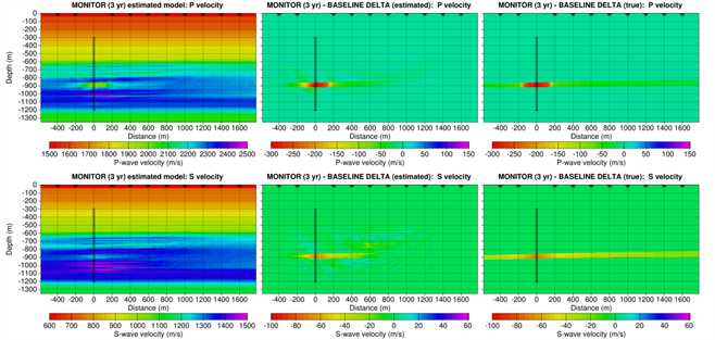
The P-wave velocity fields are displayed on the top row while the S-wave velocity fields are on the bottom row. Left, the FWI estimated models; Middle, the estimated delta between monitor and baseline; and Right, the true delta we want to retrieve. The extension of the perturbation on the right side is correct up to 300 m from the well.
Left: P-wave velocity profiles; Right: S-wave velocity profiles. The different plots correspond to different distances from the well. The starting model, denoted by the gray line, is the estimated model from the baseline FWI. The true model is denoted by the red line while P- and S-wave velocities are denoted respectively by the blue and the green lines.
Conclusions
This virtual experiment illustrates the concept of the multi-Offset VSP inversion for CO2 sequestration monitoring. It allowed us to correctly recover the P- and S-wave velocity fields for a few hundreds of meters from the well, which is a typical lateral extent of the resolution region for borehole seismic data. The accurate quantitative knowledge of P- and S-wave velocities enables us to differentiate the pore pressure and CO2 saturation effects within the reservoir. However, this experiment has been done for a perfect data set, i.e., without noise. The next stage is to validate the robustness of the method against true data.
This virtual experiment illustrates the concept of the multi-Offset VSP inversion for CO2 sequestration monitoring. It allowed us to correctly recover the P- and S-wave velocity fields for a few hundreds of meters from the well, which is a typical lateral extent of the resolution region for borehole seismic data. The accurate quantitative knowledge of P- and S-wave velocities enables us to differentiate the pore pressure and CO2 saturation effects within the reservoir. However, this experiment has been done for a perfect data set, i.e., without noise. The next stage is to validate the robustness of the method against true data.
1Tsuchiya, T., N. Yamada, U.P. Iskandar, M. Kurihara, C. Barnes and M. Charara [2017] CO2 Monitoring by using VSP-FWI: Synthetic study on CO2-saturation and Pressure-buildup differentiation. In EAGE/SEG Research Workshop on Geophysical Monitoring on CO2, Trondheim, Norway.